555 Timer Schematic Symbol : 1 To 15 Minute Timer Circuit Diagram Working And Applications - Well here are a couple of schematics the comparators are based on the trigger comparator from the actual timer schematic.
555 Timer Schematic Symbol : 1 To 15 Minute Timer Circuit Diagram Working And Applications - Well here are a couple of schematics the comparators are based on the trigger comparator from the actual timer schematic.. The diagram below the 555 die photo and schematic below are interactive. Build a 555 timer ic tone generator out of snap circuits. The 555 timer ic is an integrated circuit used in a variety of timer, pulse although we could design our own ne555 timer using these building blocks in altium it is much easier to purchase the ic and create a schematic symbol for it instead. The schematic shows the connections, but doesn't really tell you how to lay it out. Learn about the 555 timer and how it works in astable mode.
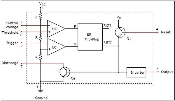
In the monostable mode, the timer generates a single pulse. Due to its relative simplicity, ease of use and low cost it has been used in literally thousands of applications. Transistor q3 is actually connected as a diode with the collector not carrying current. The circuit symbol pins are arranged to suit the circuit: The schematic shows (3) circuits, because one circuit does not work well over the entire vcc range.
Derivatives provide up to four timing circuits in one package.
In the monostable mode, the timer generates a single pulse. The 555 timer is a simple integrated circuit that can be used to make many different electronic circuits. So far i have tried drawing from this link which was supposed to produce. For standard 555 timers use timing resistor values between 1k ohms and 1m. But when i complied, i got this. The 555 timer was introduced over 40 years ago. In the mwe, two tikz objects are created that can be placed and identified as the components in schematic editors such as proteus or eagle, pins will be identified. Click on a component in the die or. Transistor q3 is actually connected as a diode with the collector not carrying current. Well here are a couple of schematics the comparators are based on the trigger comparator from the actual timer schematic. As shown in figure 12, the external capacitor is initially held discharged by a transistor inside the timer. It is a slave to timer a. The circuit symbol pins are arranged to suit the circuit:
List of simple 555 timer circuits and projects · super sensitive intruder the 555 timer is probably the most common and popular ic to be used in hobby circuits. In the schematic above, notice that the threshold pin and. Unless you are very experienced in electronics and can follow a detailed circuit such as that shown, it. The schematic shows (3) circuits, because one circuit does not work well over the entire vcc range. The circuit symbol pins are arranged to suit the circuit:
555 Timer Circuits Home Facebook from lookaside.fbsbx.com Well here are a couple of schematics the comparators are based on the trigger comparator from the actual timer schematic. This article covers every basic aspect of 555 timer ic. Derivatives provide up to four timing circuits in one package. So far i have tried drawing from this link which was supposed to produce. Now the schematic symbol and pcb symbol are created for the 555 timer. It is a slave to timer a. Usually used to create time delays. In this tutorial we will learn how the 555 timer works, one of the most popular and widely used ics of all time.
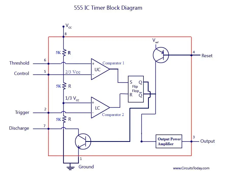
In the schematic above, notice that the threshold pin and.
5.29 shows a 555 timer configured as an astable or multistable multivibrator 66. This circuit generates a stable train of pulses. When vcc > 9v, the base to emitter junction starts to zener and. Outputs an oscillating pulse signal. 555 timer is an industrial standard ic existing from early days of ic. Derivatives provide two (556) or four (558) timing circuits in one package. The circuit symbol pins are arranged to suit the circuit: If you still need a detailed understanding of the 555 timer. Transistor q3 is actually connected as a diode with the collector not carrying current. Basically, this means that you will have a continuous transition from a high voltage level (determined by and slightly. Click on a component in the die or. In the monostable mode, the timer generates a single pulse. So far i have tried drawing from this link which was supposed to produce.
Astable Multivibrator Using 555 Timer from www.circuitstoday.com As shown in figure 12, the external capacitor is initially held discharged by a transistor inside the timer. In the mwe, two tikz objects are created that can be placed and identified as the components in schematic editors such as proteus or eagle, pins will be identified. With this information you will learn how how the 555 works and will have the experience to build some of the circuits below. List of simple 555 timer circuits and projects · super sensitive intruder the 555 timer is probably the most common and popular ic to be used in hobby circuits. In the schematic above, notice that the threshold pin and. Posted by on june 22, 2018. The 555 timer was introduced over 40 years ago. Now the schematic symbol and pcb symbol are created for the 555 timer.
The schematic shows (3) circuits, because one circuit does not work well over the entire vcc range.
Introduced in 1971 by the american company signetics, the 555 is. Well here are a couple of schematics the comparators are based on the trigger comparator from the actual timer schematic. Instead, use a lower value capacitor and a higher value resistor. It is a slave to timer a. The 555 timer is a simple integrated circuit that can be used to make many different electronic circuits. Only attach an 1k resistor + led from pin 3 to ground. 555 ic automatically switches back to stable state after some time, this time, for which the 555 stays in quasi stable state, is determined by the time constant of rc network in the circuit. When vcc > 9v, the base to emitter junction starts to zener and. N direct replacement for se555/ne555 n timing from microseconds through hours n operates in both astable and monostable modes n adjustable duty cycle n output can source or sink 200 ma n output and supply ttl compatible n schematic diagram. Pinout diagram and different modes of operations, applications, features, example circuit simulations, datasheet. But when i complied, i got this. Although a circuit common symbol is shown, the collector is not. The circuit symbol pins are arranged to suit the circuit:
In the mwe, two tikz objects are created that can be placed and identified as the components in schematic editors such as proteus or eagle, pins will be identified 555 timer schematic. It's a simple source of oscillating current that can power blinking leds, generate tones, and lots of other useful applications.


0 Komentar